Tuesday, 5 June 2012

Assembly Project 3

I started bringing the existing components from the old mouse into an assembly with the new housings. 

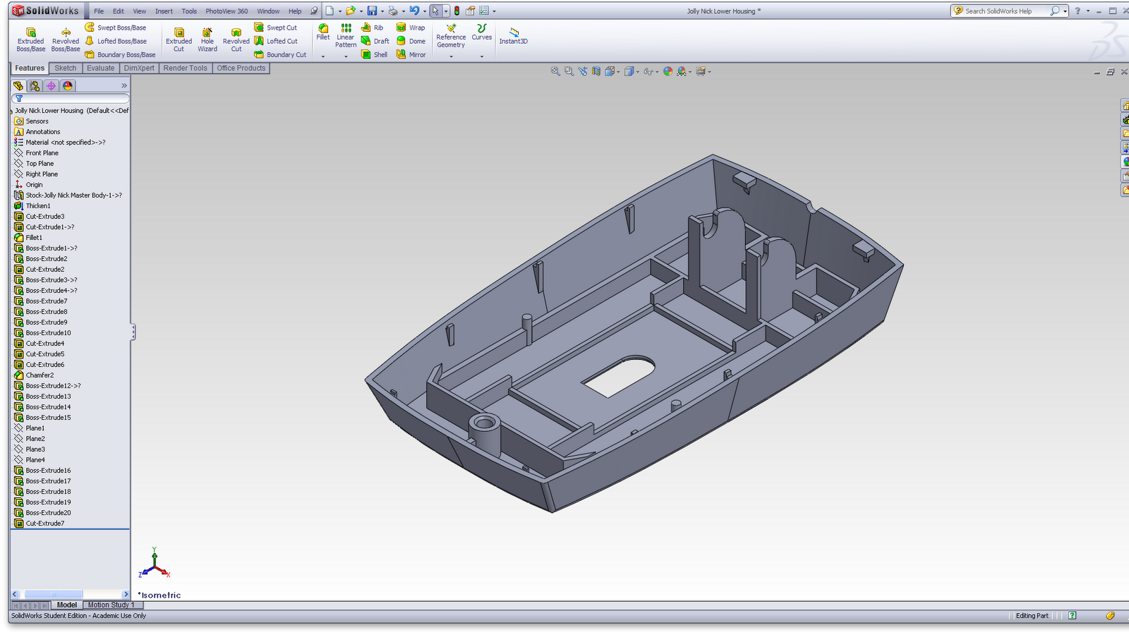
Lower housing with components

Starting to remove material from the upper housing solid body.

Adding some detail and structure running around and between the circuit board components.

The structure in the upper housing waves through the circuit board components and helps to hold it in place.

Adding details to fit the button cover


With the button cover piece - it will be made completely translucent using appearances

Cord management is very similar to that in the first mouse

Section through the middle of the mouse

Exploded view of the components

Creating solid bodies


Added thickness to the lower housing

Added some details - These were largely generated by editing the part in an assembly with the existing circuit board/wheel/lens in place.


Continued adding details including interfaces between lower and the upper housings

Used a surface fill and a surface knit to generate a solid body for the upper housing.
As this part interacts with all the others, I added details in an assembly with everything else in place.

Added thickness to the buttons cover. This will eventually become completely transparent, showing only reflected light.

Details were added in an assembly with other parts.

Developing surfaces for project 3

I decided to start by creating some ruled surfaces for the lower housing. 

This function creates a ruled surface starting from a surface edge and going in any direction to any length.

I extended the surfaces sideways and trimmed the excess to finish with a box.
These surfaces define the lower housing.

More ruled surfaces to start generating the upper housing.

Trimmed off the excess.

Side view

Added a loft to the back part of the upper housing.
Using projected curves to create crease lines for the button cover.

4 lofts and a boundary surface later...

Surface knits to create a surface body for each part, each one inserted into new part files.

Starting Assignment 3

I began this project by quickly sketching some ideas. Everything I was drawing began with a faceted base transitioning to organic curves in the upper parts.

Side views of a possible form
Side view of another form
Side view - Starting to develop the button part with faceted curved surfaces

Top view same as above

I started modelling in plasticine without much success. The symmetrical and faceted nature of the object make the form more suited to a material like polystyrene foam or a stiffer clay, but I decided to work with what I had readily available.


3/4 view showing 3 parts

Top view showing faceted curves on buttons cover

Side view showing intent for symmetrical bottom parts and a more organic top


At this point I decided to move into SolidWorks to start playing with surface functions and seeing what I could make.

Sunday, 27 May 2012

Project 2

I spent lots of time on this project and I'm very happy with my final products.

I've learned so much about surface modelling and I feel confident win my ability to model virtually any form or surface.


One thing I've noticed in the past and throughout this project is that solidworks isn't an effective design tool. It's great for CAM processes and rendering, and it can be an important step in bringing a design to reality, but I haven't found its virtual environment good for the design process.
I like to begin with the freedom that comes with a a pen and paper or physical modelling/sculpting. Solidworks requires exact dimensions from the beginning, while working on paper or physically in 3D allows for flexibility and decision changing. That said, Solidworks has some good features like the rollback bar which allows changes to be made to early features (although I often ran into errors when I used it).

I really liked using PhotoView 360 for this project. We did use it in first year but not to its full abilities - for example we were encouraged to use kitchen or factory backgrounds instead of a studio environment, weren't taught how to create cameras or to apply perspective. Working with it this year I thought it was a great tool and I was only too happy to show off my high quality surfaces.

Completing rendering, advertisement and control drawings

The next step was to produce actual photo renderings.
I found this quite easy to do, and my computer at home (slowly) produced very good images even though it struggled with the integrated preview function.

Using Photoview 360 to generate an image

I am using Parallels to run windows and Solidworks on a mac; this meant I only had one core for producing the renderings. It was a slow process.

The product.

I used one simple but powerful image to create a faux advertisement for the mouse.

I created control drawings for the mouse; just showing salient dimensions and information.

A second sheet with exploded view, isometric view and a bill of materials.

Sunday, 20 May 2012

Adding appearances and rendering

Continued to develop the assembly and added appearances to parts.

Section showing interior details and parts

Adding a decal

I tried to apply a sandblasted finish to the buttons and lower housing but couldn't quite get it right.
When I applied the texture the decal would become grainy and distorted, so I decided to leave the parts as a low-gloss plastic in the renderings. 

Starting to work on rendering