Tuesday, 27 March 2012

Pump-Action Bottle

I chose a small and fairly simple bottle for this part of the assignment.

The chosen bottle.

I made a part for the body, a part for the clear plastic cap, and an assembly for the screw-on pump lid.

The body was quite simple to make, requiring just a revolve, a screw thread and an extruded cut through the top.

Isometric of the body.

I then created an assembly for the pump lid. I decided to make and edit parts inside this assembly instead of creating each one separately and importing them at the end.

I modelled the parts I could see by simply unscrewing the lid but this was not enough. I had to break the chamber open to gain access to the valve parts. 

Some of the parts that make up the screw lid.
The chamber on the right was broken open for access.


I modelled the components within the assembly, paying attention to connections, sizing and interference between parts.

Isometric view of the lid assembly.

Section of the lid assembly.

I then created a part for the clear plastic cap within this assembly to ensure a proper fit but saved it externally. 

Separate part for the cap.

I created another assembly and imported the two parts and the lid assembly. These three components were fully mated together.

Exploded view of the bottle assembly.

This assignment was easier than I expected, I was able to get this far in the space of one afternoon and night. It seems difficult, but really it is just a series of revolves around one centre line. Creating parts inside the assembly made it much easier.

Completing Customised Bottle

I finished the customised bottle on Monday of week 5.
I had run into some issues with zero thickness geometry, needed some help sorting it out.

I ended up resolving the error by moving the top and bottom of the lid very slightly apart.

Showing open/closed configurations.

Friday, 23 March 2012

Customised Bottle

I worked on this bottle in week 4.

I started with the lid, decided to ditch the taper and elliptical base, turn it into a cylindrical shape and bring it into a more minimalist aesthetic.
I used a simple revolved sketch to achieve this.

Revolved sketch.


The shape of the old lid prevented the use of a screw-on top, but this was no longer the case and I wanted to try modelling one.
Section view showing screw thread.

 
Isometric view of the lid so far.


I then started work on the bottle body.

I started by modelling the detail of how it would attach to the lid.
Isometric view of the screw detail - this would screw into the lid.

I lofted a series of elipses to create the main bottle body.


Showing elliptical profiles and spline guide curves.

Completed loft.

I slightly extruded the very top face to create the seal. I then created a linear sketch pattern for an extruded cut.

Detail of the seal.

I wanted to create a face for any graphics or branding, and wanted to practice a lofted cut. I created a series of profiles that would cut into one face of the bottle.

Series of profiles used for a lofted cut.

This loft turned out twisted and messy, even with a guide curve.

The failed loft.

I added two more guide curves to solve the problem.

Lofting with more guide curves.

This lead to a nice neat lofted cut.

The completed lofted cut.

In-class progress Week 4

During class in Week 4 I changed the way i went about setting up the non-cylindrical bottle lid.

Instead of having the open/closed movement in the assembly I created different parts for open and closed configurations. 

Showing different parts for open and closed.

I then brought both of these into an assembly with the bottle body and created open and closed configurations.


Lid closed configuration.

Lid open configuration.

I then started to think about my Customised Bottle design.
I think that this bottle design is too busy, with too many pointless features like the finger grips - these don't actually make it easier to hold. 
With this in mind I decided to create a more minimalist and elegant bottle. 

Sketch ideation.


Monday, 12 March 2012

Non-cylindrical Bottle (lid)


On the weekend following week 3 I modelled the lid for the non-cylindrical bottle.

The lid is made from a single piece of plastic but has a hinge.


 I decided to model it as two separate parts then mate them together in an assembly.

I began with a loft to create the main body of the bottom part. I measured the width of material and the details on and around the top with a vernier caliper.

Isometric view of the incomplete lid part

I then measured and created the top part of the lid.

View of the top part of the lid

I returned to the bottom lid part and used visual approximations and logical assumptions (based on the top of the bottle body) to model the interior details. 

View of the interior details of the lid part

With the bottle body and both lid parts completed, I create an assembly to bring them together. I completely mated the bottom lid part to the main body part, preventing it from moving. 
I mated the hinge details of the two lid parts, allowing an opening/closing motion.

Isometric view of the complete bottle, with the lid slightly open

Some of the dimensions around the body lip/lid interior details needed adjusting to ensure the parts were not intersecting. 

Section view showing non-intersecting parts with lid in closed position.


Altogether this bottle took many hours to model, but I found the work interesting and actually enjoyed seeing how far I could push the program. I actually surprised myself with my skills and abilities; I would not have thought that I could produce such a complex and accurate model. 

Non-cylindrical Bottle (body)

I was able to create the main loft of the bottle body in-class, but created the lip details and lid at home.

I used the spline tool together with a combination of imported photos and a vernier caliper to produce profiles for front, side, top and bottom views. 

The front side view

At first I tried using the splines defining the sides of the bottle as 'profiles' with the top and bottom as 'guide curves' but this caused an error. I tried swapping them and was able to successfully create the loft. 

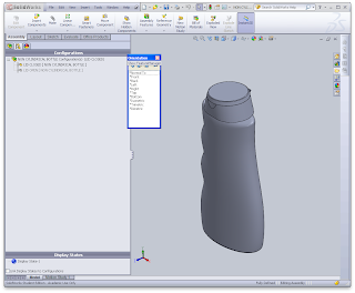
Isometric view of the lofted body

Thursday of week 2 I continued work on this bottle. 

I measured the bottle top with a vernier caliper and created accurate extrusions, then hollowed the body with the shell tool. 

Isometric view of the shelled body

I then measured the details around these extrusions and created them.

Isometric view of the bottle lip

Cylindrical Bottle

I installed SolidWorks at home mid week 2 and caught up with all classwork.

I ended up starting the cylindrical bottle again because some lines weren't meeting up and considering how much I had done it was easier than finding and fixing the problem.

This project took 2-3 hours.

Lip sketch detail

Sketch used for revolve

Isometric view of finished bottle

Sunday, 4 March 2012

forgot week 1... here we go week 2

testing testing... hope this works... started champagne bottle last week, didnt get very far, but feeling quite confident with my skills.

Planning on installing solidworks at home tonight, should make things easier!